
Managing objects in the project

 English

 Italiano
NavigationThis 360section takesexplains youhow insideto create objects within the project. Objects can be 360vector photosgeometries, takensuch duringas apoints, survey,lines soor polygons, or non-vector objects, known as forms.
Object types
In the project you can walkcreate different types of objects:
Single elements that can be placed in the 2D and 3D views, such as sensors or markers.
Lines
Sequences of connected points forming paths, such as infrastructure routes.
Polygons
Areas delimited by multiple vertices, such as work zones or perimeters.
Forms
Non-vector objects, without geometry, used to enter data through
Any data entered in the platform is managed on an on-premise cloud infrastructure, unless different agreements have been made with the provider. It is always possible to download all project asdata iflocally youand weredelete any associated media at any time. For further support on sitedata insteadmanagement, ofcontact flying over its point cloud.helpdesk@eaglearca.it
Creating objects
Form (non-vector objects)
To1. get started, look forOpen the explorerInventory view at the bottom of the map,desired object class.
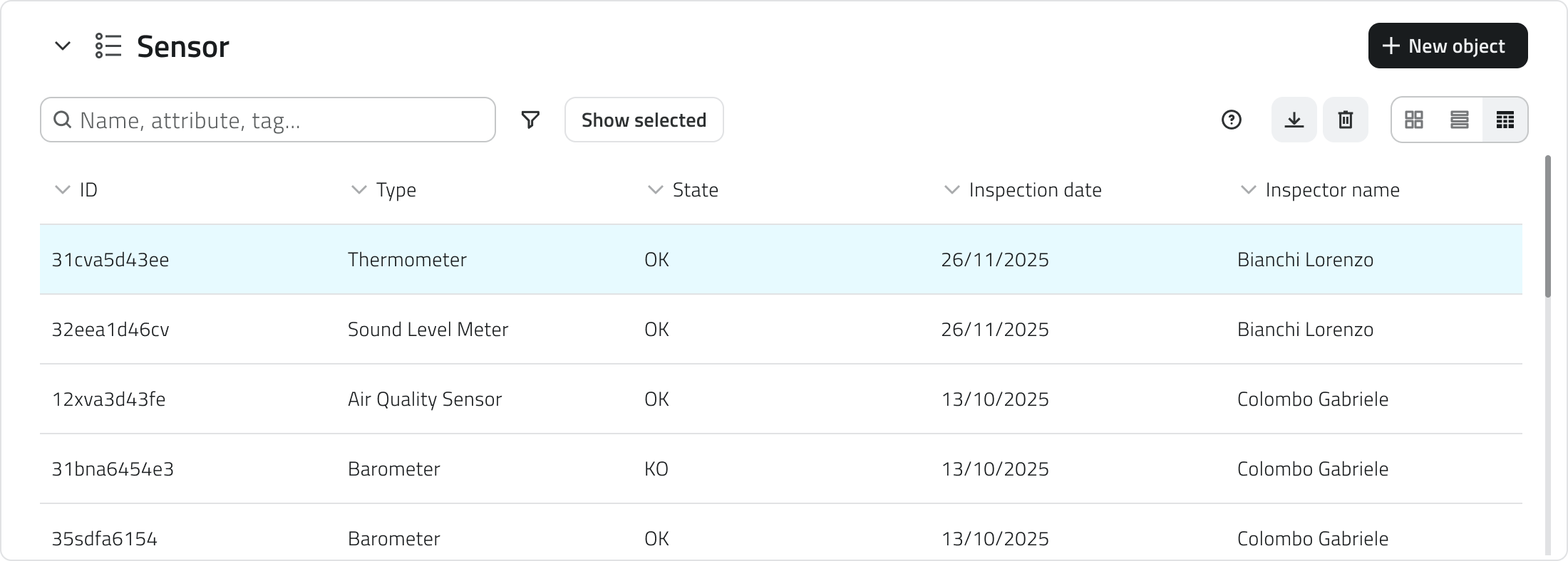
2. Click the New object button in the top-right corner.
3. The attribute panel opens for data entry.
Geometries (vector objects)
1. Hover over the 2D or 3D view to reveal the toolbar, then select the Draw tool.
2. To choose the object class, click the arrow next to the basemaptool. selector.Use the search bar at the top of the list to filter quickly, you can see a style preview to help with the selection.
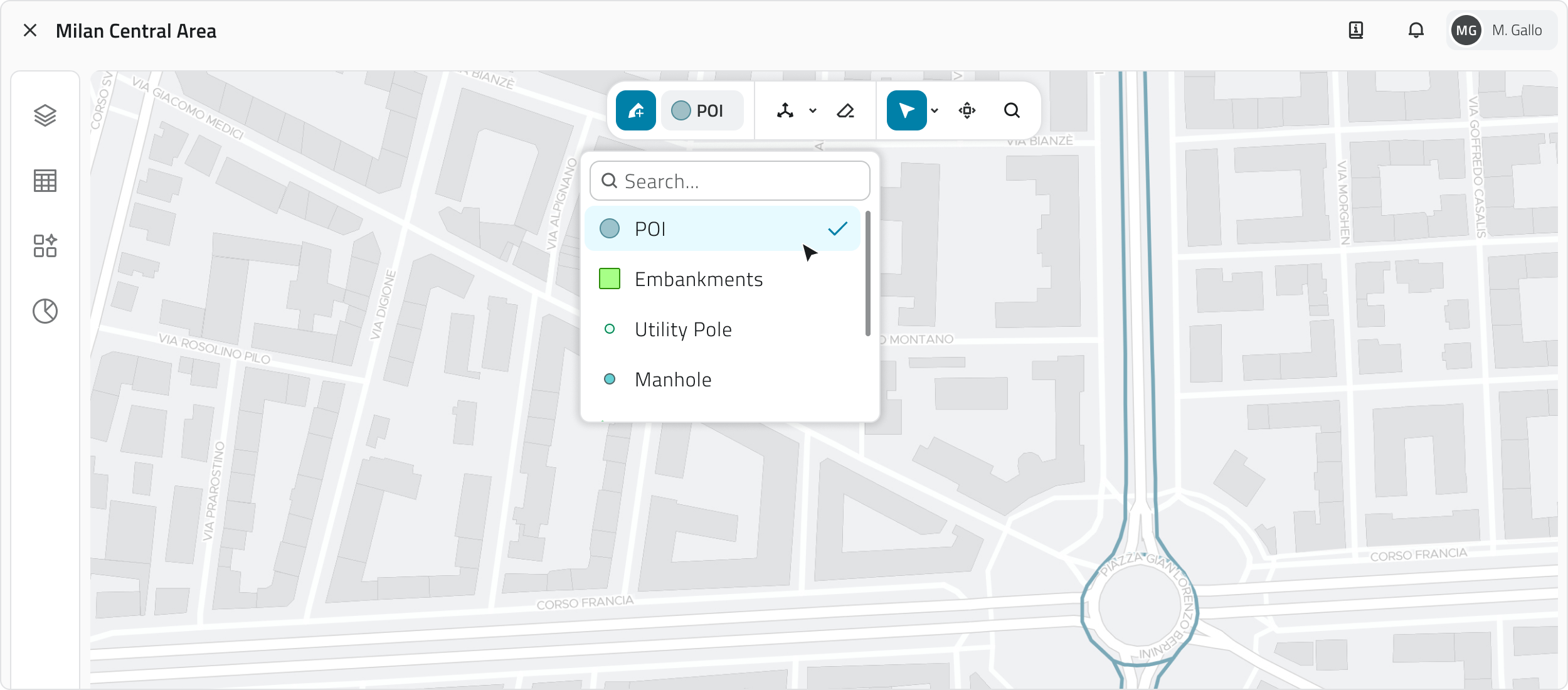
3.
Entering a photo
PressDraw the explorerobject
Point
Click with the pathsleft mouse button.
Line
To add vertices, click with the left mouse button; to close the geometry, click with the right mouse button.
Polygon
Polygon To add vertices, click with the left mouse button; after the third vertex the polygon preview appears. To close the geometry, click with the right mouse button.
n the 3D view, objects must be created on the surface of the mesh or point cloud.
4. Once the geometry is confirmed, the attribute panel opens.
Automatic object creation
Some object classes can be configured from the Backoffice to create objects automatically.
When this function is active, it is indicated by a dedicated icon in the following places:
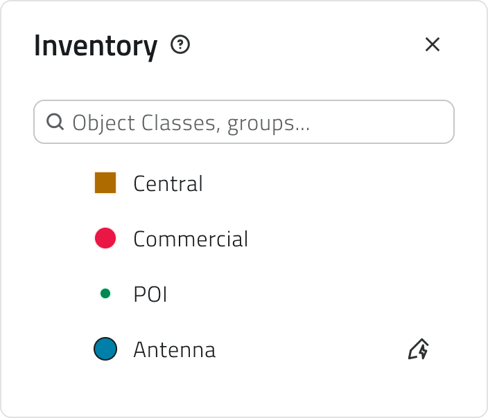
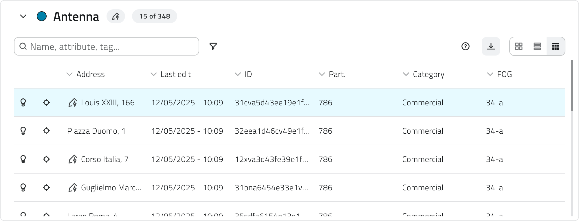
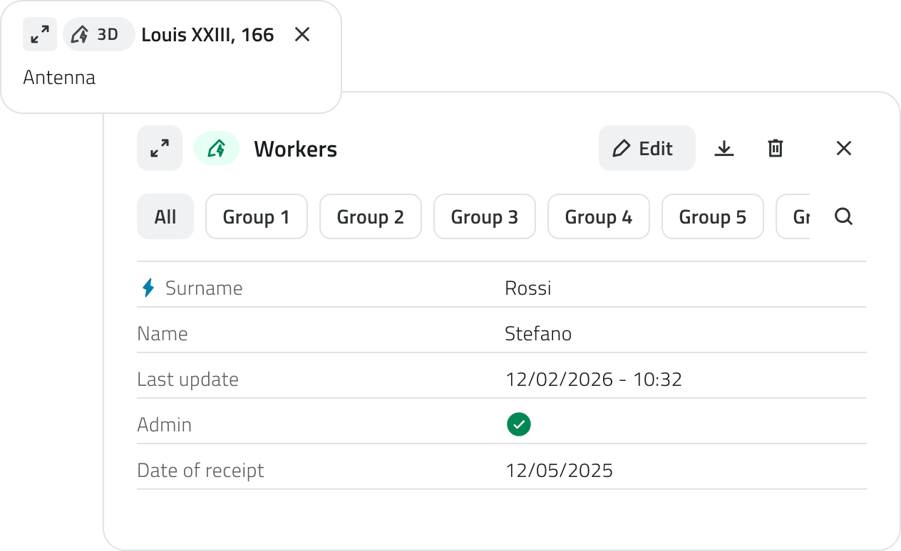
ReleaseAutomatically created objects can be edited and, if needed, also created manually within the explorersame object class.
Filling in attributes
After creation, the attribute panel allows you to enter the required information.
The object cannot be saved until all required fields have been filled in.
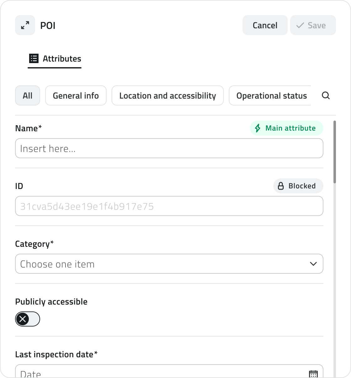
At the top left is the Expand button to open the photo.panel in full screen. The 3DCancel viewand expandsSave buttons are positioned at the top right.
If the object class has attributes organised into groups, tabs appear at the top of the panel that allow you to fullfilter screen,attributes whileby category. Clicking on a tab shows only the 2Dattributes mapbelonging becomesto that group. Next to the groups there is a button to expand the minimapsearch bar.
Attribute types
Objects can have the following attribute types:
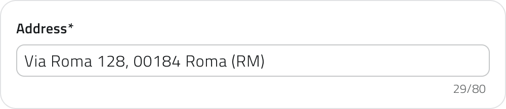
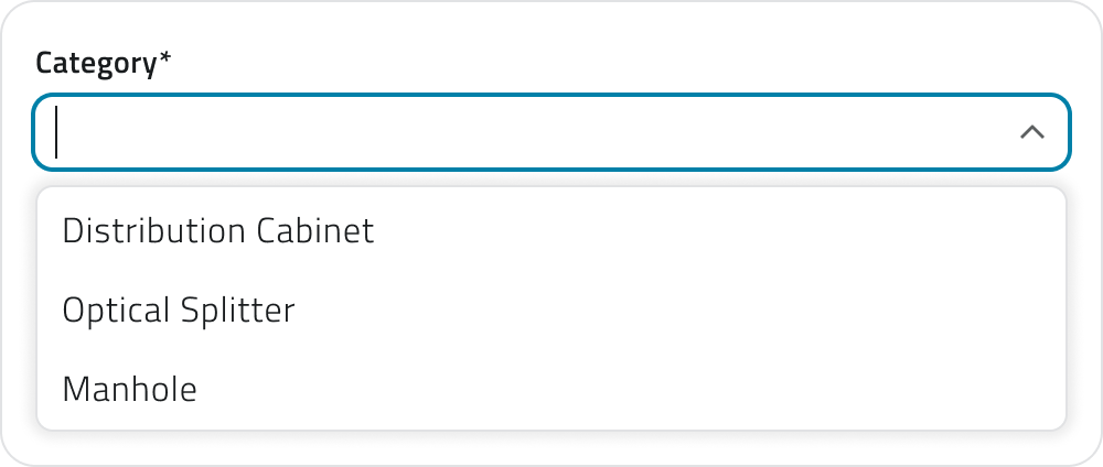
Numbers: Numeric values (possible predefined range).
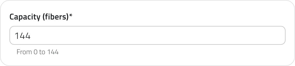
Value list: Selection of one or more values from a dropdown menu.
Date: Selection of a date or date and time.

Attachments: Upload of images, documents or videos.

Size: (Vector only) Automatically calculated by the system (coordinates/length/area).

True/False: Choice between the two true/false values.

Object list: Addition of related sub-attributes (can be of type Text, Numbers, Value list, Date, True/False).
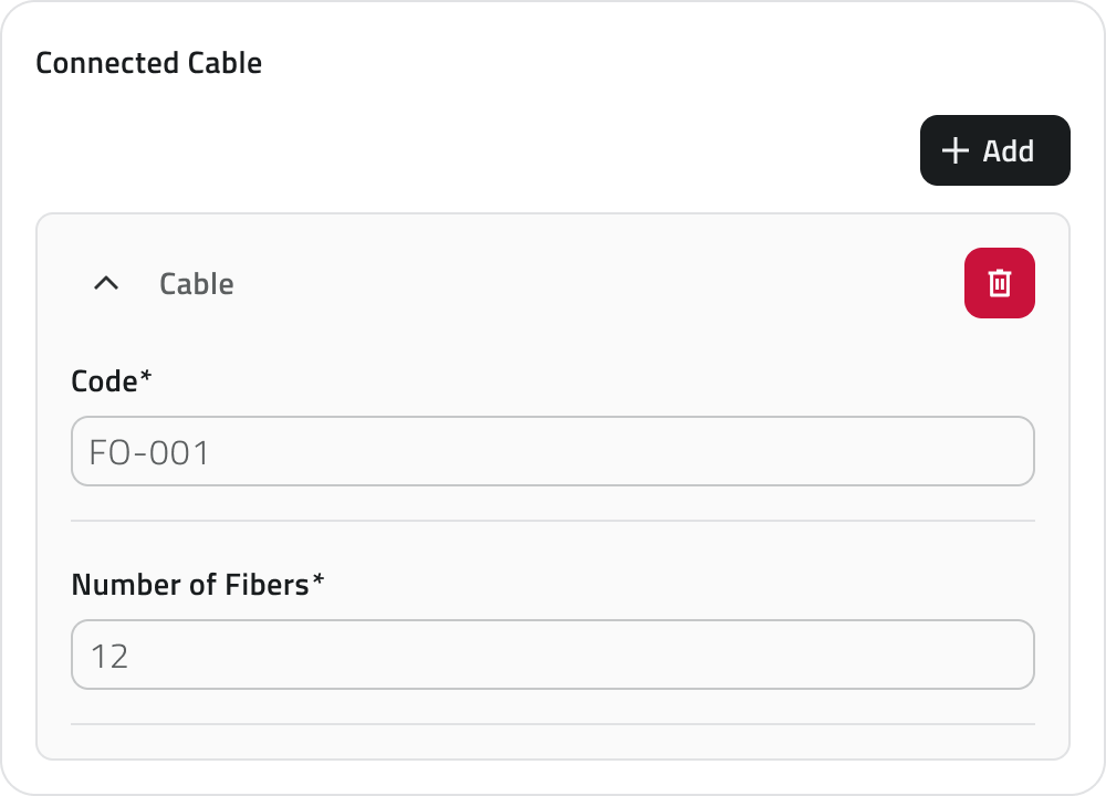

Some attributes may be pre-filled with a default value: in this case they may already be ready for saving or locked and not editable.
💡 Tip: use the search bar in the cornerattribute ofpanel to quickly find the screen.
Thefield. explorerMake andsure itsthat directionany conepre-filled helpvalues youin findmandatory your bearings, showing where youfields are andcorrect whichbefore way you are looking. The 360 photo markers, red and camera-shaped, show where the other 360 photos are.saving.
Attribute
Moving between photos
Once inside a photo, you can move between 360 photos in several ways:
LeavingAssigning a data source to an object
Available only with sensors already associated with the photoproject.
A data source is a source that collects data over time; associated with an object, it allows you to display that data as charts in the Attribute details panel.
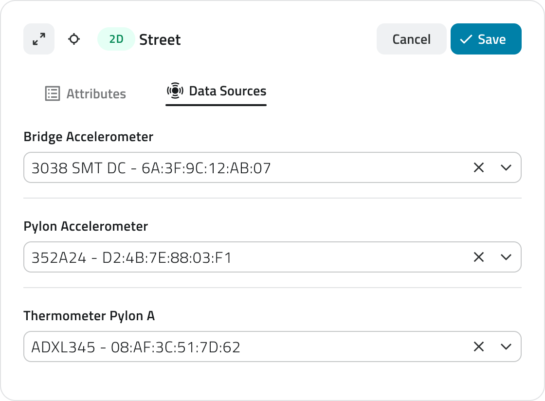
It is possible to assign a data source at two different points: during object creation or afterwards by editing an existing object.
Assignment during creation
1. During object insertion, the attribute details panel opens in configuration mode.
3. Click the selection field and choose one of the available options from the list.
Assignment during editing
1. Open the Attribute details panel of the object by clicking the blue Open button that appears when hovering over the element in the Inventory view, or select it in the 2D or 3D view and click Expand in the info card.
2. Click the Edit button.
4. Click the selection field and choose one of the available options from the list.
Managing and editing objects in the 2D view
ToThis leavesection provides guidance on moving, rotating, editing vertices and deleting objects.
Moving an object
The Move tool allows you to reposition selected objects with precision.
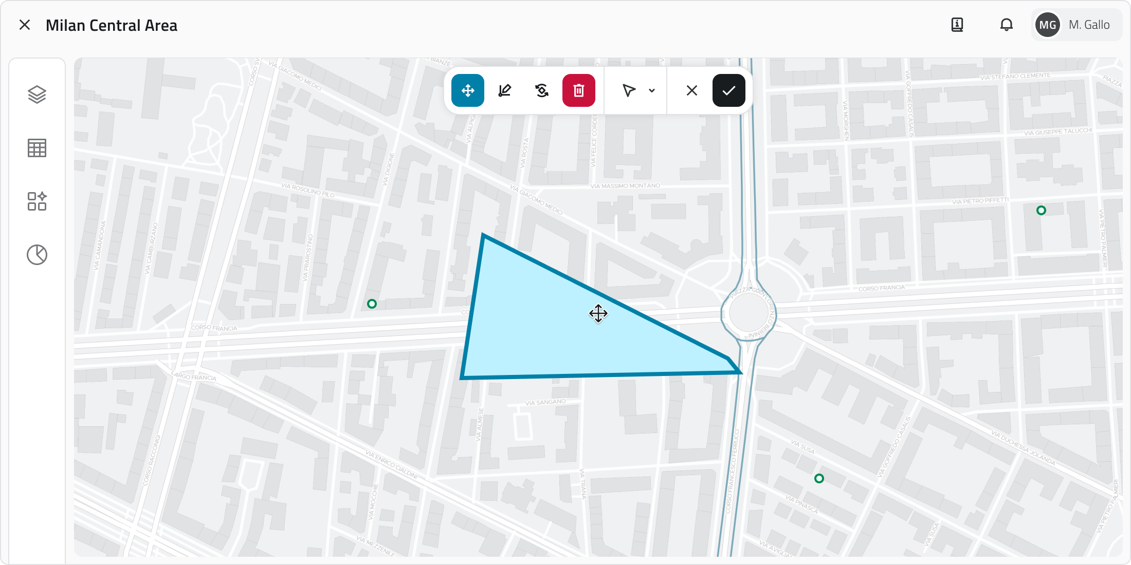
1. Select one or more objects.
2. Click the photoMove button in the toolbar.
3. Grab and freely move the object; snap with other objects on the map is supported.
4. To save the new position click Confirm. If the object has not been moved the button remains disabled. To restore the original position click Cancel.
Rotating an object
Rotation modifies the orientation of Line or Polygon objects.
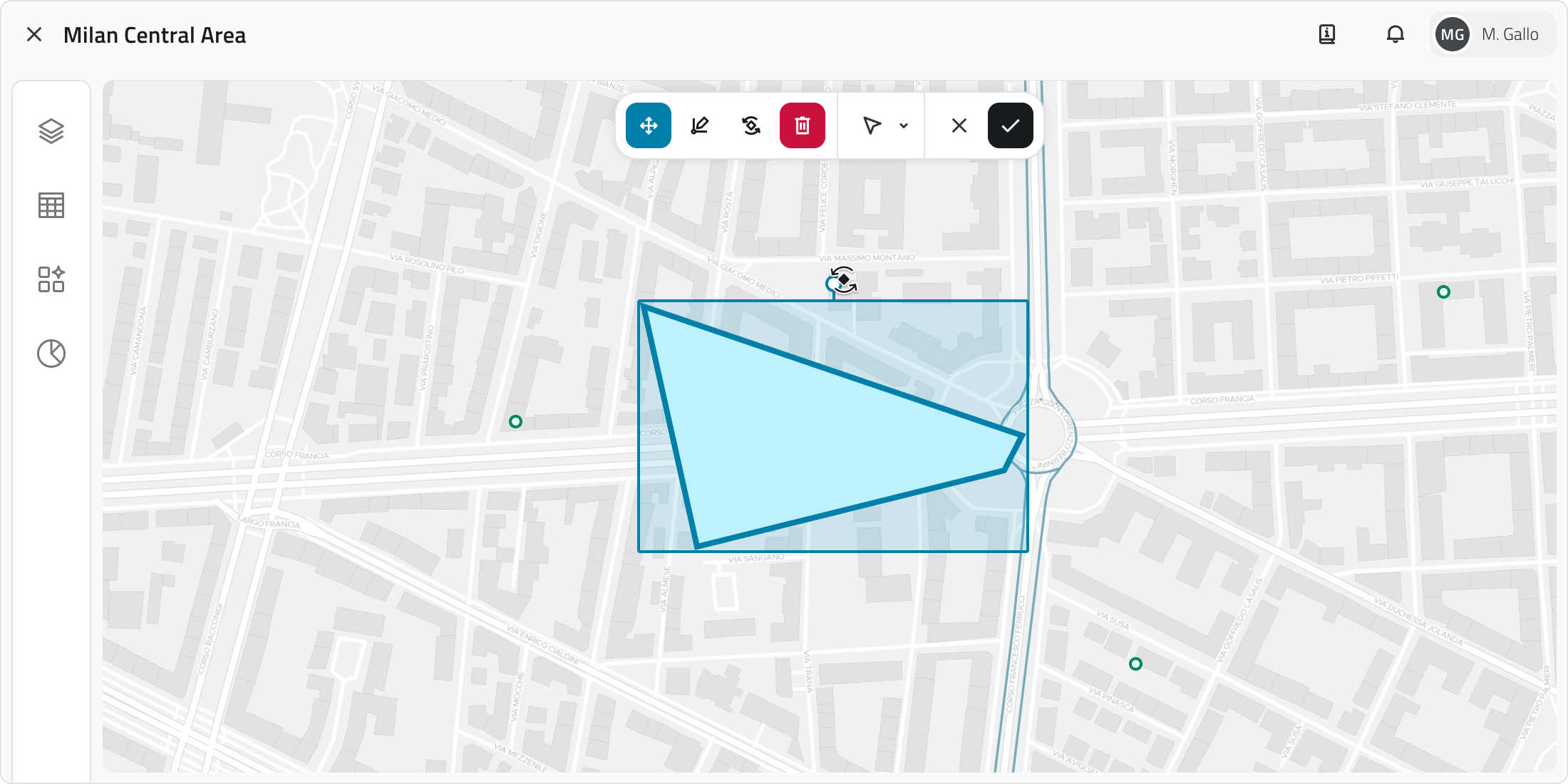
1. Select one or more objects.
2. Click the Rotate button in the toolbar. A rectangle with a handle appears around the object.
3. Drag the handle to rotate the object. Multiple rotation occurs around the central pivot point.
4. To save the new orientation click Confirm. If the object has not been rotated the button remains disabled. To restore the original orientation click Cancel.
Editing object vertices
This tool allows you areto in,move, add or correct the vertices of Lines and Polygons.
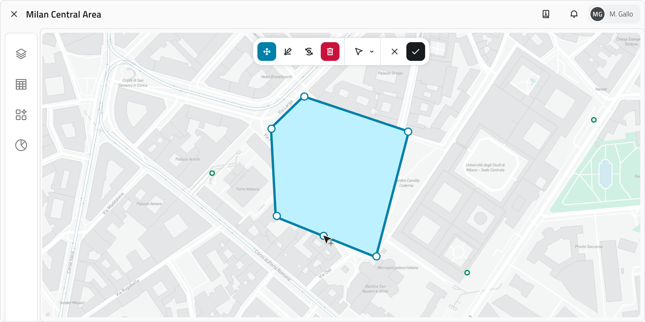
1. Select a line or polygon.
2. Click the Edit vertices button in the toolbar. All vertices become visible.
3. Drag an existing vertex to move it. To add a new vertex, click the closemidpoint that appears along the segment. Snap with other geometries is supported.
4. To save the changes click Confirm. If the object has not been modified the button remains disabled. To restore the original shape click Cancel.
Deleting an object
This function permanently deletes the selected objects in all views.
1. Select one or more objects in the 2D, 3D or Inventory view. In the Inventory view, hold CTRL and click to add objects to the selection or remove them from it.
2. Click the Delete button: in the 2D and 3D views it is located in the toolbar, in the Inventory view at the top rightright.
3. A window opens with the list of object classes involved in the selection, each with a checkbox.
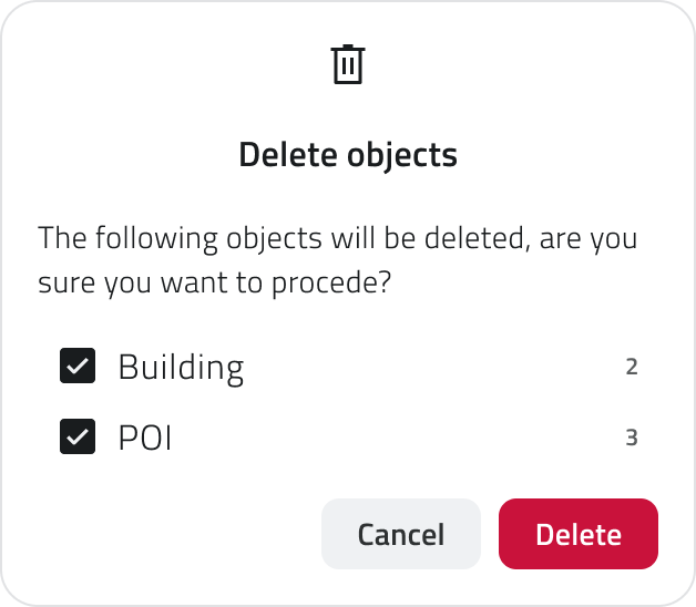
4. Select the checkboxes corresponding to the objects to delete.
5. Click Confirm to proceed, or Cancel to close the window without making any changes. The Confirm button is disabled if all checkboxes are deselected.
At the end of the 3Doperation view:a younotification goappears back aboveat the pointbottom cloud.

💡 lightTip: bluealways band coveringcheck the surveyed ground.
Either way, to get back inside a photo, click one of the 360 photo markerscheckboxes in the 3Dconfirmation viewwindow orbefore drag the explorer onto a path again.
Resources
The photos belongproceeding to theavoid resourcesdeleting ofunwanted the Layers panel. If you hide a resource, its path leaves the map and, if you were inside one of its photos, the view moves to the nearest photo still visible.objects.
Links
Introduction to Object Classes Navigating between views

EsplorareGestione undegli oggetti nel progetto in navigazione 360
LaQuesta sezione spiega come creare oggetti all’interno del progetto. Gli oggetti possono essere navigazionegeometrie 360vettoriali, come punti, linee o poligoni, oppure oggetti non vettoriali, detti form.
Tipi di oggetti
Nel progetto puoi creare diverse tipologie di oggetti:
Elementi singoli posizionabili nelle viste 2D e 3D, come sensori o segnaposto.
Linee
Sequenze di punti collegati per formare percorsi, come tracciati di infrastrutture.
Poligoni
Aree delimitate da più vertici, come zone di lavoro o perimetri.
Form
Oggetti non vettoriali, senza geometria, usati per inserire dati tramite attributi, come moduli informativi.
Qualsiasi dato immesso in piattaforma viene gestito su un’infrastruttura cloud on-premise, a meno di differenti accordi con il fornitore. È sempre possibile scaricare in locale tutti i dati del progetto ed eliminare qualsiasi media associato in qualsiasi momento. Per ulteriore supporto alla gestione dati, contatta l'indirizzo helpdesk@eaglearca.it
Creazione di Oggetti
Form (Oggetti non vettoriali)
1. Apri la vista Inventory tidella classe oggetto desiderata.
2. Clicca sul pulsante Nuovo oggetto in alto a destra.
3. Si apre il pannello attributi per la compilazione dei dati.
Compilazione degli Attributi ↓
Geometrie (Oggetti vettoriali)
1. Passa con il mouse sulla vista 2D o 3D per far comparire la barra degli strumenti, quindi seleziona lo strumento Disegna.
2. Per scegliere la classe oggetto clicca sulla freccia accanto allo strumento. Usa la barra di ricerca in cima alla lista per filtrare rapidamente, puoi vedere l'anteprima dello stile per facilitare la selezione.
3. Disegna l’oggetto sulla mappa:
Punto
Clicca con il tasto sinistro del mouse.
Linea
Per inserire i vertici, clicca con il tasto sinistro del mouse, per chiudere la geometria, clicca con il tasto destro.
Poligono
Per inserire i vertici, clicca con il tasto sinistro del mouse, dopo il terzo vertice appare l'anteprima del poligono. Per chiudere la geometria, clicca con il tasto destro.
Nella vista 3D gli oggetti devono essere creati necessariamente sulla superficie della mesh o della nuvola di punti.
4. Confermata la geometria, si apre il pannello attributi.
Compilazione degli Attributi ↓
Creazione automatica degli oggetti
Alcune classi oggetto possono essere configurate dal Backoffice per creare oggetti in automatico.
Quando questa funzione è attiva, è segnalata da un'icona dedicata individuabile nei seguenti punti:
In caso di creazione automatica, l'etichetta, con solo l'icona, sarà disponibile anche per oggetti di tipo Form.
Gli oggetti creati automaticamente possono essere modificati e, se necessario, creati anche manualmente nella stessa classe oggetto.
Compilazione degli Attributi
Dopo la creazione, il pannello attributi permette di esplorareinserire le informazioni richieste.
L'oggetto non può essere salvato finché tutti i fotocampi 360°obbligatori scattatenon durantesono compilati.
In alto a sinistra si trova il pulsante Espandi per aprire il pannello a schermo intero. I bottoni Annulla e Salva sono posizionati in alto a destra.
Se la classe oggetto ha attributi organizzati in gruppi, nella parte superiore del pannello compaiono delle schede che permettono di filtrare gli attributi per categoria. Cliccando su una scheda vengono mostrati solo gli attributi appartenenti a quel gruppo. Accanto ai gruppi è presente un rilievo,pulsante muovendotiper all'internoespandere la barra di ricerca.
Tipi di Attributi
Gli oggetti possono avere i seguenti tipi di attributi:
Testo: Lettere e numeri (possibile lunghezza massima).
Numeri: Valori numerici (possibile range predefinito).
Lista valori: Selezione di uno o più valori da un menu a tendina.
Data: Scelta di una data o data e ora.
Allegati: Caricamento di immagini, documenti o video.
Dimensione: (Solo vettoriali) Calcolata automaticamente dal sistema (coordinate/lunghezza/area).
Vero/Falso: Scelta tra i due valori vero/falso.
Lista oggetti: Aggiunta di sotto-attributi correlati (possono essere di tipo Testo, Numeri, Lista valori, Data, Vero/Falso).
Per iniziare, cercalungo il pulsantesuo Explorertracciato).
Entrare in una foto
Premi il pulsante Explorer: sulla mappa compaiono i percorsi delle foto disponibili, rappresentati da linee azzurre che seguono gli itinerari del rilievo. I percorsi compaiono anche trascinando l'Explorer sulla mappa.
Avvicina l'Explorer a un percorso: si aggancerà automaticamente alla foto più vicina e comparirà un piccolo riquadro con un'anteprima di ciò che stai per visualizzare.
RilasciaAlcuni l'Explorerattributi possono essere precompilati con un valore di default: in questo caso potrebbero essere già pronti per aprireil salvataggio oppure bloccati e non modificabili.
💡 Suggerimento: usa la foto.barra Ladi vistaricerca 3Dnel sipannello espandeattributi aper schermotrovare intero, mentre la mappa 2D diventa una minimappa nell'angolo dello schermo.
L'Explorer erapidamente il conocampo direzionaledesiderato. tiVerifica aiutanoche ai orientarti,valori mostrandoprecompilati lanei tuacampi posizioneobbligatori esiano lacorretti direzione in cui stai guardando. I marker foto 360, rossi e a formaprima di fotocamera, indicano invece la posizione delle altre foto 360°.salvare.
Proprietà degli
Spostarsi tra le foto
Una volta entrato in una foto, puoi spostarti tra le foto 360° in diversi modi:
UscireAssegnare dallaSorgenti fotodati ad un oggetto
Disponibile solo con sensori già associati al progetto.
Una sorgente dati è una fonte che raccoglie dati nel tempo; associata a un oggetto, consente di visualizzare tali dati come grafici nel pannello Dettaglio attributi.
È possibile assegnare una sorgente dati in due momenti distinti: durante la creazione dell'oggetto oppure in un secondo momento modificando un oggetto già esistente.
Assegnazione in creazione
1. Durante l'inserimento dell'oggetto si apre il dettaglio attributi in configurazione.
2. Spostati nella sezione Sorgente dati.
3. Clicca nel campo di selezione e scegli una delle opzioni disponibili dall'elenco.
Assegnazione in modifica
2. Clicca sul pulsante Modifica.
3. Spostati nella sezione Sorgente dati.
4. Clicca nel campo di selezione e scegli una delle opzioni disponibili dall'elenco.
Gestione e modifica di oggetti nella vista 2D
Questa sezione fornisce le indicazioni relative allo spostamento, alla rotazione, alla modifica dei vertici e all'eliminazione degli oggetti.
Spostare un oggetto
Lo strumento Sposta consente di riposizionare con precisione gli oggetti selezionati.
1. Seleziona uno o più oggetti.
2. Clicca sul pulsante Sposta nella barra degli strumenti.
3. Afferra e sposta liberamente l'oggetto; è supportato lo snap con altri oggetti sulla mappa.
4. Per usciresalvare dallala fotonuova corrente,posizione clicca Conferma. Se l'oggetto non è stato spostato il pulsante rimane disabilitato. Per ripristinare la posizione originale clicca Annulla.
Ruotare un oggetto
La rotazione modifica l'orientamento di oggetti di tipo Linea o Poligono.
1. Seleziona uno o più oggetti.
2. Clicca sul pulsante Ruota nella barra degli strumenti. Appare un rettangolo con una maniglia attorno all'oggetto.
3. Trascina la maniglia per ruotare l'oggetto. La rotazione multipla avviene attorno al punto di pivot centrale.
4. Per salvare il nuovo orientamento clicca Conferma. Se l'oggetto non è stato ruotato il pulsante rimane disabilitato. Per ripristinare l'orientamento originale clicca Annulla.
Modificare i vertici di un oggetto
Questo strumento consente di spostare, aggiungere o correggere i vertici di Linee e Poligoni.
1. Seleziona una linea o un poligono.
2. Clicca sul pulsante Modifica vertici nella barra degli strumenti. Tutti i vertici diventano visibili.
3. Trascina un vertice esistente per spostarlo. Per aggiungere un nuovo vertice, clicca sul punto intermedio che compare lungo il segmento. È possibile usare lo snap con altre geometrie.
4. Per salvare la modifica clicca Conferma. Se l'oggetto non è stato modificato il pulsante dirimane chiusuradisabilitato. Per ripristinare la forma originale clicca Annulla.
Eliminare un Oggetto
Questa funzione elimina definitivamente gli oggetti selezionati in tutte le viste.
1. Seleziona uno o più oggetti nella vista 2D, 3D o Inventory. Nella vista Inventory, tieni premuto CTRL e clicca per aggiungere oggetti alla selezione o toglierli.
2. Clicca sul pulsante Elimina: nelle viste 2D e 3D si trova nella barra degli strumenti, nella vista Inventory in alto a destradestra.
3. Si apre una finestra con l'elenco delle classi oggetto coinvolte nella vistaselezione, 3D.ciascuna Torneraicon cosìuna alla vista dall'alto della nuvolacasella di punti.spunta.
Per4. passareSeleziona allale caselle corrispondenti agli oggetti da eliminare.
5. Clicca navigazioneConferma liberaper procedere, oppure Annulla, cliccaper invecechiudere sulla finestra senza apportare modifiche.
Il pulsante Explorer.Conferma Sullaè mappa,disabilitato ise percorsitutte vengonole sostituiticaselle dall'improntasono deldeselezionate.
Al termine dell'operazione compare una fascianotifica azzurrain chebasso evidenziaa sinistra con l'areaesito rilevata.dell'eliminazione.
In💡 entrambiSuggerimento: icontrolla casi,sempre puoile rientrare in una foto cliccando su uno dei marker foto 360caselle nella vista 3D oppure trascinando nuovamente l'Explorer su un percorso.
Risorse
Le foto sono associate alle risorse disponibili nel pannello Layers. Se nascondi una risorsa, il relativo percorso scompare dalla mappa. Se ti trovi all'internofinestra di unaconferma delleprima suedi foto,procedere laper visualizzazioneevitare passadi automaticamenteeliminare allaoggetti fotonon visibile più vicina.desiderati.
Collegamenti
Introduzione alle Classi Oggetto Navigare tra le visteLast update: 2122 OctoberMay 2026